Re-signing a IPA file

|

I just had the task to figure out why we had an App crashing randomly on us all of the sudden. The App is distrubuted through AppCenter only, as a Enterprise build. Turned out that the provisioning profile had expired hence it started to fail.

Now, I did not want to build a new version of the App, since the one distributed and in production is much older and we are in the middle of moving CI for the App into a new enviroment. So the only option was to sign the App again with the new provisioning profile. So here are some notes on how I did that.

The prerequisites for this are:

  • IPA file to re-sign
  • Distribution certificate is installed in your KeyChain
  • mobileprovision file to sign with
  • a macOS installation with Xcode installed (I used 11.3.1)

The following snippets are commands you would run in your preferred commandline.

First we need to unizp the IPA file. It will contain a Payload folder with AppName.app inside, where AppName is your App’s name. I will use MyApp as an example throughout this post. Yours will of course be different.

unzip MyApp.ipa

You should now have a Payload folder where contents were extracted.

First we need to extract the entitlements for the App, we will need them later when we are signing the App again.

codesign -d --entitlements :- "Payload/MyApp.app" > entitlements.plist

This will create a entitlements.plist file in the folder you are currently in. If you are re-signing the App with a distribution certificate for another team, remember to change identifiers in the entitlements file to match your distribution certificate.

Now before we re-sign the App, we need to remove the old code signing.

rm -r Payload/MyApp.app/_CodeSignature

We also need to replace the provisioning profile. Assuming your profivisioning profile file name is called MyApp.mobileprovision and is located in the same folder we are in.

cp MyApp.mobileprovision Payload/MyApp.app/embedded.mobileprovision

We should now be ready to re-sign the Application.

codesign -f -s "iPhone Distribution: your team name here" --entitlements entitlements.plist Payload/MyApp.app

Now we just need to zip the folder and we are ready to distribute it.

zip -qr MyApp-resigned.ipa Payload

That is it! You are ready to ship your re-signed App!

Connecting to WiFi in Android 10

|

Android 10 was recently released and it introduces a bunch of changes in terms of Privacy. This means that access to /proc/net from the Linux sub-system has been restricted, which requires you to use NetworkStatsManager and ConnectivityManager to get VPN information.

It adds restrictions to who is allowed to enable/disable WiFi. We could previously use WifiManager.SetWifiEnabled(), but not anymore, this method will return false. You will need to show one of the new Settings Panels, which shows a slice of the Android Settings within your App.

What this post will focus on is the restrictions to access to configured networks and connecting to networks. A bunch of the network API has changed, so let us look a bit into what we have available now.

Suggesting networks

Something new to Android 10 is suggesting networks to connect to. These are just hints to the platform that the networks you provide it, can be connected to and it might decide to chose one of them. When any of these networks are detected nearby, Android will show a notification to the user the first time, which is how they allow connecting to a suggested network.

This could be useful for an Enterprise App, which can allow Access to networks depending on the logged in user or suggest a separate network for guests.

You can suggest networks like so.

var guestUsers = new WifiNetworkSuggestion.Builder()
    .SetSsid("GuestNetwork")
    .SetWpa2Passphrase("hunter2")
    .Build();

var secretEnterpriseNetwork = new WifiNetworkSuggestion.Builder()
    .SetSsid("Cyberdyne")
    .SetWpa2Passphrase(":D/-<")
    .Build();

var suggestions = new[] { guestUsers, secretEnterpriseNetwork };

var wifiManager = this.GetSystemService(Context.WifiService) as WifiManager;
var status = wifiManager.AddNetworkSuggestions(suggestions);

if (status == NetworkStatus.SuggestionsSuccess)
{
    // We added suggestions!
}

The suggestions you provide can only be added once. If you try add the same suggestion again, the status from AddNetworkSuggestion will return SuggestionsErrorAddDuplicate. If you need to modify a suggestion, you need to remove it first with  RemoveNetworkSuggestion, then add the modified version of it again. Additionally, in order to add these suggestions you will need to add the CHANGE_WIFI_STATE permission to your AndroidManifest.xml.

<uses-permission android:name="android.permission.CHANGE_WIFI_STATE" />

Note: Some of the options on a WifiNetworkSuggestion requires you to request Fine Location permission in order to work. Make sure to consult the Android documentation to be sure.

After you run AddNetworkSuggestion don’t expect something to happen immediately. There will eventually be a notification in the notification drawer. Which looks like something in the image below. Choosing “Yes” on the notification, won’t necessarily automatically connect to the network. However, going to Wifi Settings on your device, it should now know how to connect to that network.

suggestion notificationsuggestion wifi settings

Connecting to Specific Networks

Prior to Android 10, we could explicitly tell Android to connect to a specific Network and it would simply do it. This was done using WifiManager.AddNetwork() where you provided a WifiConfiguration. Now this API has been deprecated and replaced with ConnectivityManager.RequestNetwork, where you build a Network Request with a Wifi Specification, similar to the suggestions I showed you above. However, it also allows you to specify, whether the connection requires Internet, cannot be VPN, has to be WiFi and more.

You will also need to provide a ConnectivityManager.NetworkCallback, which will let you know whether connection to the network was successful or not. The idea here is that you are awaiting the requested network to connect and only when that is successful you can continue with your execution.

This is excellent for scenarios, where you need to be on a specific network to do some specific operations. One thing to note is that you will only be able to connect to this network while the App is open. As soon as the App is closed, it disconnects the network.

Note: this connection will not have any Internet connectivity according to the Google docs. See the notes in the Android documentation about WiFi Bootstrapping. For Internet connectivity Google suggests to use the Network Suggestions described above.

Let us look at some code.

var specifier = new WifiNetworkSpecifier.Builder()
    .SetSsid("cyberdyne")
    .SetWpa2Passphrase("ill be back")
    .Build();

var request = new NetworkRequest.Builder()
    .AddTransportType(TransportType.Wifi) // we want WiFi
    .RemoveCapability(NetCapability.Internet) // Internet not required
    .SetNetworkSpecifier(specifier) // we want _our_ network
    .Build();

var connectivityManager = this.GetSystemService(Context.ConnectivityService) as ConnectivityManager;

connectivityManager.RequestNetwork(request, callback);

Here is an example of wanting to connect to the network with SSID “cyberdyne” and passphrase “ill be back”. The transport type specifies what kind of network you want to connect to. In this case it is a WiFi network. We do not require any Internet capability on the network. Per default it requests Internet, Not VPN and Trusted capabilities.

The callback looks something like this.

private class NetworkCallback : ConnectivityManager.NetworkCallback
{
    public Action<Network> NetworkAvailable { get; set; }

    public override void OnAvailable(Network network)
    {
        base.OnAvailable(network);
        NetworkAvailable?.Invoke(network);
    }
}

var callback = new NetworkCallback
{
    NetworkAvailable = network =>
    {
        // we are connected!
    }
};

You can also use OnUnavailable to detect that we could not connect to the network in particular, or the user pressed cancel.

Connect to Device Request

If you connect once to a network request, any subsequent requests will automatically connect if you are in range of the network and the user will not have accept it again. Also, while the App is open and you want to disconnect from the requested network, you simply call ConnectivityManager.UnregisterNetworkCallback() on the callback.

This hopefully gives you an idea about how to connect to WiFi Networks with Android 10.

You can check out the code from my Android 10 WiFi Repository on GitHub and have a go at playing with it yourself.

Talking to a Xiaomi Mijia Temperature Sensor

|

I have a colleague who showed me these lovely Xiaomi Mijia high precision temperature sensors, which can tell you the temperature and air humidity. They are battery powered and they broadcast their information through Bluetooth Low Energy (BLE).

Xiaomi Mijia Sensor

My colleague had some issues reading out the values the sensors broadcast over BLE, so I took it up as a small challenge to figure out how to read the values out in a Xamarin.Android App.

For the task I chose to use NuGet package Plugin.BLE, which I have used before for some other projects with great success. Lots of praise to Sven-Michael Stübe, who is the author behind the plugin. A lot of work has gone into making it and he made it very nice to work with, providing a an easy to use API, which works on both Xamarin.Android and Xamarin.iOS.

So first things first. In order to be allowed to scan for BLE devices on Android, you have to request the Location permission. For this I employ the trusty Permissions Plugin. Here I can request the permission like so:

private async Task<bool> RequestPermissions()
{
    if (DeviceInfo.Platform != DevicePlatform.Android)
        return true;

    try
    {
        var status = await CrossPermissions.Current.CheckPermissionStatusAsync(Permission.Location);
        if (status != PermissionStatus.Granted)
        {
            var requestStatus = await CrossPermissions.Current.RequestPermissionsAsync(Permission.Location);
            if (requestStatus.ContainsKey(Permission.Location))
            {
                return requestStatus[Permission.Location] == PermissionStatus.Granted;
            }
        }
    }
    catch (Exception ex)
    {
        //Something went wrong
    }

    return false;
}

Now that we have a way to get permission to scan for BLE devices, we can start scanning for BLE broadcasts.

var ble = CrossBluetoothLE.Current;
var adapter = CrossBluetoothLE.Current.Adapter;
adapter.DeviceDiscovered += OnDeviceDiscovered;

As you can see, in 3 lines of code we have set up our code to get discovered devices. In the OnDeviceDiscovered method we get a model describing the BLE device, including advertisement records and much more. We will use the advertisement records later to get the values from the Mijia Sensor.

Since this App is only interested in Xiaomi Mijia devices, we can provide a filter for the BLE plugin, such that we limit our search to such devices only. The Xiaomi Mijia devices I have all advertise themselves as “MJ_HT_V1”. Hence, I created a simple filter, checking for that name.

private bool DeviceFilter(IDevice device)
{
    if (device.Name?.StartsWith("MJ_HT_V1") ?? false)
        return true;

    return false;
}

Then we can start scanning for devices by calling:

adapter.ScanMode = ScanMode.LowLatency;
await adapter.StartScanningForDevicesAsync(null, DeviceFilter, cancellationToken: token);

I have ensured that the ScanMode is Low Latency, just notice that this scan mode uses a lot of power.

Scanning for devices start popping up the devices I have. Now to the fun part parsing the advertisement records the Xiaomi Mijia is sending. From reading a bunch of other clever people reverse engineering the device protocol I figured out that the Xiaomi Mijia sends out 4 different kinds of advertisement records. These can be identified by reading the 14th byte in the advertisement record. Then reading the subsequent bytes and piece them together to a value.

Byte 14 Type of value Bytes to read
0x04 Temperature 17 + 18
0x06 Humidity 17 + 18
0x0A Battery 17
0x0D Temperature and Humidity temp: 17 + 18
hum: 19 + 20

The read values have to be combined and then divided by 10.0 for battery and humidity to get the values in degrees Celsius and humidity percentage.

So typically these advertisement records would look like:

95 FE 50 20 AA 01 57 29 AE 33 34 2D 58 0D 10 04 DB 00 CC 01 which corresponds to 21.9 degrees C and 46% humidity.

95 FE 50 20 AA 01 5E 29 AE 33 34 2D 58 06 10 02 CB 01 which is 45.9% humidity.

Parsing the data I ended up with a method looking something like this:

private (double battery, double? temperature, double? humidity) ReadServiceData(byte[] data)
{
    if (data.Length < 14) return (-1, null, null);

    double battery = -1;
    double? temp = null;
    double? humidity = null;

    if (data[13] == 0x04) //temp
    {
        temp = BitConverter.ToUInt16(new byte[] { data[16], data[17] }, 0) / 10.0;
    }
    else if (data[13] == 0x06) //humidity
    {
        humidity = BitConverter.ToUInt16(new byte[] { data[16], data[17] }, 0) / 10.0;
    }
    else if (data[13] == 0x0A) //battery
    {
        battery = data[16];
    }
    else if (data[13] == 0x0D) //temp + humidity
    {
        temp = BitConverter.ToUInt16(new byte[] { data[16], data[17] }, 0) / 10.0;
        humidity = BitConverter.ToUInt16(new byte[] { data[18], data[19] }, 0) / 10.0;
    }

    if (temp.HasValue)
        System.Diagnostics.Debug.WriteLine($"Temp: {temp.Value}");
    if (humidity.HasValue)
        System.Diagnostics.Debug.WriteLine($"Humidity: {humidity.Value}");

    System.Diagnostics.Debug.WriteLine($"Battery: {battery}");

    return (battery, temp, humidity);
}

Piecing all of this together in a little MvvmCross App, yielded me something like seen in this screenshot.

Android App Screenshot

You can find the entire source code for the App on GitHub.

Make Your Own Azure DevOps Build Light

|

Click to watch the YouTube video: ESP8266 Azure DevOps build light

I had a colleague at a previous work place, which had made a Philips Hue light, light up red when our bamboo build of our Xamarin Apps was failing, light up green if everything was OK. This is a pretty good way to have a visual indicator in the entire team if something is being checked in which is failing our builds. I decided to give this a go as well. However, with a Micro Controller Unit (MCU) instead, since it costs much less than a Philips Hue setup and it will require less moving parts. Philips Hue would need something else on the network telling it which color to switch to. With the MCU I would just need that.

I have had spoken to a friend about making such a light. He has been dabbling a bit himself with home automation and MCUs himself. He told me he had the right stuff for me to try out and play with. So, he have me a WeMos D1 mini, a ESP8266 based MCU, a NeoPixel ring (a.k.a. W2812) with 8, individually controllable LEDs and a little box to house it in. He himself had made a remotely controllable night lamp out of similar parts.

So my journey began into the world of MCUs and how to control the LED ring I have had gotten. Just like with mobile Apps, there are so many possibilities. A vast amount of libraries, frameworks and operating systems for all sorts of purposes. I fell over something called PlatformIO, which allows me to do everything from Visual Studio Code! Writing the code, building it, deploying it, debugging it by stepping around in the code etc. Additionally it has a library manager for libraries that other people have written. Neat!

OK! Let us get started making our own build light. Getting the status from Azure DevOps can be done through their REST API calling the Builds API. In order to do this you need to generate a Personal Access Token, which you include in the header for the GET request. You can read more about how you authenticate in the REST API docs. In my case I have 4 build agents that can run at any given time. So I want the top 4 builds and see what the status is for them. This can be done by querying the following URL: https://dev.azure.com/{organization}/{project}/_apis/build/builds?$top={top}&api-version=5.0, where {organization} is the name of your organization, {project} is the ID of the project you want to query within and {top} being the count of items I want in return. You can decrease the scope further down to specific build definitions and more. However, project and organization are required parameters.

When quering this data from Azure DevOps I quickly realized that the returned payload was huge! My ESP8266 only has a couple of MB of RAM and deserializing that huge piece of payload on the MCU was not working at all. Right! Now what? Since I cannot tell the Azure DevOps query that I am only interested in the status of the last 4 builds and not in any of the other properties I had to introduce some middleware of some sort. Just needed something quick without too many bells and whistles and to do minimal work on the MCU itself.

Azure Functions to the rescue! I quickly whipped up a simple Azure Function that gets the status of the builds and returns the following to my MCU:

  • failing if any of the last 4 builds had failed
  • running if any of the last 4 builds are running
  • finished if all the last 4 builds have completed and succeeded

So getting the last 4 builds amounts to this little piece of code:

private static async Task<IEnumerable<Build>> GetLatestBuild(int top = 4)
{
    var client = EnsureHttpClient();
        
    var url = $"https://dev.azure.com/{organization}/{project}/_apis/build/builds?$top={top}&api-version=5.0";
    
    var response = await client.GetAsync(url).ConfigureAwait(false);
    using (response)
    {
        if (response.IsSuccessStatusCode)
        {
            var responseStream = await response.Content.ReadAsStreamAsync().ConfigureAwait(false);
            using (responseStream)
            using (var streamReader = new StreamReader(responseStream))
            using (var jsonReader = new JsonTextReader(streamReader))
            {
                var serializer = new JsonSerializer();
                var results = serializer.Deserialize<Builds>(jsonReader);
                
                return results.Builds.Take(4);
            }
        }
    }
    
    return null;
}

From those builds I can now check the status with a little bit of LINQ gymnastics:

var anyFailed = lastBuild.Any(b => b.Status?.ToLowerInvariant() == "failed");
var anyRunning = lastBuild.Any(b => b.Result.ToLowerInvariant() == "inprogress");
var allFinished = lastBuild.All(b => b.Result.ToLowerInvariant() == "succeeded" && b.Status?.ToLowerInvariant() == "completed");

Then return the status depending of the status of these. For these statuses I want to light up the LEDs:

  • Red if returned status is failed
  • Blue if returned status is running
  • Green if returned status is finished

OK. Now I can get a small payload for the MCU to chew on. To communicate with the Azure Function, we need a HTTP client of some sort for this I am including the WiFiClientSecure.h headers, these come with with PlatformIO when targeting the ESP8266. The code for downloading the status is a little bit more involved than you might be used to from C# or other managed languages.

First you need to connect to the host, in my case: buildlight.azurewebsites.net. The port is 443 since it is HTTPS.

WiFiClientSecure client;

bool connect() {
  Serial.print("connecting to ");
  Serial.println(host);

  bool ok = client.connect(host, httpsPort);

  Serial.println(ok ? "Connected Http" : "Connection Http Failed!");
  return ok;
}

When the connection is all good we can then send our request. The request in this case is whatever comes after the host part of the url: /api/{FunctionName}?code={apiCode} where {FunctionName} is the name of the function you are calling and {code} the code generated in the Azure Portal for calling your function. So we are sending a request that looks like:

GET {request} HTTP/1.1
Host: buildlight.azurewebsites.net
User-Agent: Cheesebulb/1.0
Connection: close
void sendRequest() {
  client.print("GET ");
  client.print(request);
  client.println(" HTTP/1.1");
  client.print("Host: ");
  client.println(host);
  client.println("User-Agent: Cheesebulb/1.0");
  client.println("Connection: close");
  client.println();
}

Now we are only interested in the body of the response and not the headers, so we skip these:

void skipHeaders() {
  while (client.connected()) {
    String line = client.readStringUntil('\n');
    if (line == '\r') {
      Serial.println("headers received");
      break;
    }
  }
}

Skipping these is reading until you get a carriage return \r. Now reading the rest will be the body of the request.

String status = client.readStringUntil('\n');

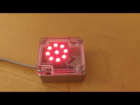
Now that we have the status let us shine some light!

The NeoPixels work by providing 5V to a 5V pin and ground to a GND pin. They usually have a DI and DO pin, which are how you tell them which color they should light. The DI pin is the input pin and the DO pin is to chain it to more pixels. So essentially you are only communicating through one pin. For the NeoPixels this happens by sending a 800Hz digital signal on that pin, which can address each individual pixel, neat! The more pixels, then longer it takes to update the pixels. However, in my case with 9 pixels, this does not matter at all! Before you start powering your NeoPixels, I suggest you read some general best practices about these. You can damage them if not handled correctly. In my case I added a 1000µF capacitor between the 5V and ground pin to eat up any surges. This is especially importan if you power your NeoPixels using a DC adapter. However, this also helps if you need to change a lot of pixels at the same time and the amount of current drawn by the pixels suddenly changes.

To control the NeoPixels through the MCU I use the NeoPixelBus library. I have connected my NeoPixel ring to the RX pin. You might notice there are a lot of other digital output pins on the ESP8266. However, they operate at 3.3V and the NeoPixel require a 5V signal. The RX pin on my module is different and is in normal circumstances used for serial input to the MCU. However the NeoPixelBus library supports sending data on this pin using Direct Memory Access (DMA) mode. It requires more memory, but uses significantly less CPU.

In any case, on the ESP8266 to change colors on the LEDs I use the following code.

const uint8_t PixelCount = 9;
const uint8_t PixelPin = 0; // doesn't matter what you put here

NeoPixelBus<NeoGrbFeature, NeoEsp8266Dma800KbpsMethod> strip(PixelCount, PixelPin);

// define some colors
RgbColor off(0, 0, 0);
RgbColor red(255, 0, 0);
RgbColor green(0, 255, 0);
RgbColor blue(0, 0, 255);

Setting the color off a pixel is just a matter of calling:

strip.SetPixelColor(pixelIndex, color);

So setting pixel 2 to green you call: strip.SetPixelColor(1, green), the index starts at 0.

If you are interested in seeing the rest of the code I wrote for this little project you can check out this gist with all of it.

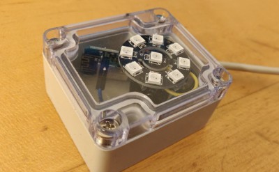
Here is a beauty shot of the device.

picture of ESP8266 with a NeoPixel ring in a box

With some basic programming knowledge and a MCU and some LEDs you can make this project on your own. I have only scratched the surface with what you can use a MCU for. I might return in the future with more fun projects. But for now, I can now see a nice visual status of my Xamarin App builds when I am at the office, without having to open a web page and check it there. In addition I have ordered a big white salt crystal which is going to rest over the box so it will act as both a build light and a piece of decoration for the office!

The cost of this little project is around $10, which is significantly less than getting started with Philips Hue or some other remotely controlled light.

Some Common ConstraintLayout Pitfalls and Mistakes

|

Recently I have been working a lot with converting nested layouts, into flattened layouts using ConstraintLayout as their root element.

If you do not know what ConstraintLayout is all about, in short terms, it is a layout that allows to position and size views in a flexible manner. It is in some ways similar to RelativeLayout. However, it gives you more power by allowing you to use percentages for sizes, chaining views together and much more.

Since I have been working with it quite a bit, I would try to highlight some common mistakes that people make when using ConstraintLayout. Also, help you avoid some pitfalls you can encounter on your. Hopefully, this will help you improve your own layouts.

Do not use match_parent for widths and heights

When you use ConstraintLayout, you are constraining your view dimensions using rules. These rules are a family of attributes that you apply on your view, starting with layout_constraint. There are various constraints, such as:

layout_constraintTop_toTopOf
layout_constraintStart_toStartOf

A common mistake is to use match_parent for layout_width and layout_height. However, what you instead should use is 0dp which means *match contstraints*, because ConstraintLayout the entire idea about this layout is that you apply constraints to size and position your views.

Instead of match_parent for width, you would instead use the following two rules:

app:layout_constraintStart_toStartOf="parent"
app:layout_constraintEnd_toEndOf="parent"

Where parent is the encapsulating view, in this case it would be the ConstraintLayout. However, instead of writing parent it could be the ID of another view in the layout.

Now, match_parent will work and do what it does in other layouts. However, on some older versions of ConstraintsLayout it is not recommended to use it, since it is not entirely supported. Make sure you are using version 1.1 or newer.

What about wrap_content?

wrap_content is still valid for layout_width and layout_height and will be respected by ConstraintLayout.

A thing to note though. If you use wrap_content and for instance the two rules, from the match_parent example above like:

<View
    android:layout_width="wrap_content"
    app:layout_constraintStart_toStartOf="parent"
    app:layout_constraintEnd_toEndOf="parent"
    ...

The view will not match the entire width of the parent. What you instead are describing here is that the view wraps its width, but should be positioned between the start and end of the parent. This is useful with couple of other attribute called layout_constraintHorizontal_bias and layout_constraintVertical_bias.

Let us say you want to postion a view at a third of the screens width. You would apply the following constraints like so:

<View
    android:layout_width="wrap_content"
    app:layout_constraintHorizontal_bias="0.3"
    app:layout_constraintStart_toStartOf="parent"
    app:layout_constraintEnd_toEndOf="parent"
    ...

Pretty neat!

Broken chains

ConstraintLayout allows you to create a chain between multiple views. This can help you with things like:

  • Equally spreading chained views
+                                                      +
|    +----------+     +----------+     +----------+    |
|    |          |     |          |     |          |    |
|    |          +----->          +----->          |    |
<----+  View A  |     |  View B  |     |  View C  +---->
|    |          <-----+          <-----+          |    |
|    |          |     |          |     |          |    |
|    +----------+     +----------+     +----------+    |
+                                                      +

For this effect you need to apply layout_constraintHorizontal_chainStyle="spread" or layout_constraintHorizontal_chainStyle="spread_inside" on View A. The latter will not add spacing at the start of View A and at the end of View C. There is also a Vertical variant of this chain style.

  • Weigh views similarly to what LinearLayout can do
+                                   +
|+----------++---------------------+|
||          ||                     ||
||  Weight  +>        Weight       ||
<+   0.25   ||         0.75        +>
||          <+                     ||
||          ||                     ||
|+----------++---------------------+|
+                                   +

Apply layout_constraintHorizontal_weight or layout_constraintVertical_weight on all elements in the chain to add weights.

  • Packing together views
+                                                    +
|        +----------++----------++----------+        |
|        |          ||          ||          |        |
|        |          +>          +>          |        |
<--------+  View A  ||  View B  ||  View C  +-------->
|        |          <+          <+          |        |
|        |          ||          ||          |        |
|        +----------++----------++----------+        |
+                                                    +

Some of the variants can have bias applied to them to increase or decrease the effects on elements. Say you want to spread equally, except for the center view, which needs more space.

If you notice the small ascii drawings above, in between all of the views there is a directional arrow. In order to create a chain, you need to create constraints that position your views bi-directional. So if you have views A, B and C. A must have a constraint to a parent or another view and to B. In turn B must a constraint to A and to C. At last C must have a constraint to B and to another view or parent. If you forget to constraint bi-directinally, your chain is broken and the effect you want to achieve will not work.

So compared to RelativeLayout which does not allow to add circular positioning between views ConstraintLayout actually allows this in order to create these chains.

Setting Guideline percentages based on screen size and orientation

ConstraintLayout has a couple of virtual layouts, which are not visible on the screen at all. Guideline being one of the. Guidelines are useful for positioning start, end, top and bottom constraints on a view against it.

A guideline can be set at a fixed position using layout_constraintGuide_begin="100dp" which will position it at 100dp at the left or top of a view. Or you can alternatively use layout_constraintGuide_end="100dp", which will postion the Guideline at 100dp to the right or bottom of a view.

A guideline can also be positioned at a percentage of the width or height of the view with layout_constraintGuide_percent="0..1" where 0 is left, 0.5 is middle and 1 is right.

One cool thing is that you can use Android’s values folder structure to provide dimensions for different screen sizes for these guidelines. For instance on a phone you want to have a view fill most of the screen, while on a table you may want to to only fill half of the screen.

This is easy to set up for dimensions specified in dp. However, for the percentages, it is slightly different. Plain dimens on Android do not allow you to use floating point values.

Imagine you have a folder structure as follows:

Resources
    values
        dimens.xml
    values-sw600dp
        dimens.xml

You would put your normal phone resources into values/dimens.xml while you would put your tablet resources into values-sw600dp/dimens.xml.

Regular dimens for typed values like sp, dp, px can be added to a dimens.xml file like so:

<?xml version="1.0" encoding="utf-8"?>
<resources>
  <dimen name="guidelineBegin">16dp</dimen>
</resources>

This can be consumed for your Guideline like so:

<android.support.constraint.Guideline
    android:layout_width="wrap_content"
    android:layout_height="wrap_content"
    android:orientation="vertical"
    app:layout_constraintGuide_begin="@dimen/guidelineBegin" />

The dimension added in values/dimens.xml will be substituted by the value in values-sw600dp/dimens.xml if the sw, smallest width is 600dp or more. There are other values folders you can use, which you can read more about in the Android App resources overview.

Dimensions which are float values, normally need to be followed by a typed value sp, dp, etc. In order to add percentages we can use for Guidelines, these need to be specified slightly differently like so:

<?xml version="1.0" encoding="utf-8"?>
<resources>
  <item name="fiftyPercent" type="dimen">0.5</item>
</resources>

These can still be consumed as normal dimensions like so:

<android.support.constraint.Guideline
    android:layout_width="wrap_content"
    android:layout_height="wrap_content"
    android:orientation="vertical"
    app:layout_constraintGuide_percent="@dimen/fiftyPercent" />

Should you use ConstraintLayout for all your layouts?

ConstraintLayout is very powerful and allows you to create complex layout, without a nested hell of views. Often it can be much more performant than a deeply nested layout. However, should you use it even for the simplest layouts? Obviously it really depends on the use case. However, it should be noted that all this power does not come for free. There is some overhead in calculating positions and sizes for views in your layout when using ConstraintLayout. Hence, in many cases using a flattened layout with RelativeLayout as root, may outperform ConstraintLayout. So, in the end it is a question of the complexity of the layout and how much of the power ConstraintLayout provides you want to utilize.

There are various benchmarks out there. Make sure the benchmark you read include both inflation-, layout- and measure-time. Also you may find that performance differs significantly between versions benchmarked as improvements find their way into ConstraintLayout over time. You can read more about the performance benefits on the Android Developers Blog.

Hopefully you found some of this information useful.